autocad lisp routine draw 3d poline to nearest points
This command allows you lot to find areas indicating an internal betoken between objects or by selecting airtight contours, this command shows the area obtained or otherwise sets it in a selected text.
The Ax command has the following options:
Initial requests:
Specify an internal point of the area or [Select object / Options] :
Here you must indicate the internal points from which the area volition be obtained, the other options are described below:
Select object: Instead of specifying internal points to detect airs, y'all can select airtight polygons to observe your surface area.
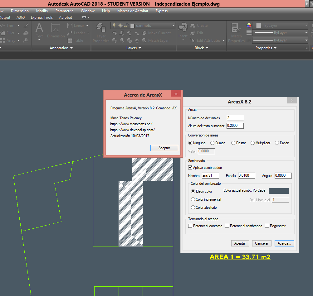
Options: This selection loads the Control Options dialog box, the dialog box is as follows:
Each choice is described beneath:
Number of decimals: The number of decimal places the area volition have (2 by default).
Height of text to insert: If y'all decide to insert a text with the area obtained, here is set the pinnacle that will take said text.
Conversions of areas: This option allows y'all to perform operations with the values of the areas found, each area is added, subtracted, multiplied or divided by a factor that must be specified in the lower part of this option.
The command shows if the conversion is active and which of the operations is carried out and with what value the conversion will be carried out.
This option allows you to customize the areas when the drawing is in different scales or in other cartoon units.
Apply shading: This option allows each indicated surface area to be shaded to have a better view of the area that is being found, thus assuasive to verify if it is correct (Enabled by default).
Name of the shading: Here you must indicate the name of the shading to exist applied in the indicated areas (Solid default).
(Shading) Calibration: Here the scale factor of the shading is indicated, this factor is variable co-ordinate to the blazon of shading selected.
Colour (shading): The color that the shading volition accept applied in the indicated areas.
Finishing the shading: The options beneath utilize one time the control application is terminated.
Hold contours: If enabled the generated contours are non deleted.
Hold shading: If enabled the generated shadings are not deleted.
Final Requests:
Specify an internal betoken of the area or [Select object / Insert area text / Options] :
Insert text surface area: This option allows y'all to insert a text with the obtained area instead of selecting i to replace information technology. The text with the expanse plant has the default prefix: " Area =", this prefix can exist modified in the programme code.
Change text: This option is activated when the Enter key is pressed or the right mouse button is pressed, which will asking a text to be selected, for example if there is a text with the post-obit content: "AC=0.00m2" and through the command an area of 3.25 has been found, then the command will supercede the text, updating it to "AC=3.25m2". As you can meet, AX replaces but the numeric values of the text to exist replaced, then you can have area texts with different prefixes, for case: "AR=0.00m2", "AM=0.00m2", "Cut expanse =0.00m2", "My area=0.00m2", etc.
Valid and invalid outlines:
Valid outline
To apply this routine yous must exercise the following:
- Load the lisp file in AutoCAD.
- Enter the proper name of the command: AX
- Indicate an internal signal in the area yous want to find (you accept to brand sure that the area to be found must exist completely closed, otherwise the command will display an mistake message).
- Indicate internal points as many times as you need, the command will rage, accumulating (summing) all the airs found.
- Press Enter or right-click to stop the command and set the surface area in an existing text.
Y'all tin can become the routine here!
This small routine performs the same as the previous ane, the difference is that the name of the layer is not entered here to select the objects, but an entity is selected from which you lot want to obtain the name of the layer.
As in the previous routine, the selection of entities is not fabricated visible, only it exists as a prepare of selected entities, and so the selection mode must exist indicated "Previous" to select the objects.

To use this routine you must do the following:
- Load the lisp file in AutoCAD.
- Enter the proper name of the control: ssl
- Select the object you desire to get the layer proper noun to select the other entities
- Make effective the option of entities by means of the predictive style
You can go the routine here!
Using this routine you can delete the objects that are in the inner or outer surface area of a selected polyline, if the option is indicated, the objects that are intersected by the polyline will be cut past the side indicated.
When information technology comes to removing objects outside the polyline, special care should exist taken as This command deletes all objects outside the polyline.

The polyline to select Must be a closed polyline, otherwise the routine joins the last point of the segment with the first, Closing thus by means of an imaginary line the polyline and eliminating everything that is inside or outside that line.
The pick cut equally information technology is logical, but works with objects that tin can be cut manually, As for example, lines, circles, arcs, etc, blocks and other compound objects do not fit inside these objects that can be cutting out.
With the lisp a sample file is attached So that the corresponding tests are done before using the control in last files.
To use the routine yous must do the following:
- Load the lisp file in AutoCAD.
- Enter the proper name of the command: PolErase
- Select polyline Which volition serve equally an edge to delimit the objects to eliminate.
- Choose ane delete objects option, you tin cull the option: Window (it only deletes objects that are totally exterior or inside that window), Capture (Removes objects that are even intersected past the edge of the polyline), delete and crop (As the proper noun implies, it will erase objects that are inside or outside the polyline and trim objects that intersect the edge.
- Indicates a point on which side (internal / external) will erase or trim objects.
You can become the routine here!
Information technology is a lisp routine that allows yous to select all entities that are in the indicated layer, does not distinguish color or other property that may take the entity.
This routine is not case sensitive at the time of inbound the proper noun of the layer, and so yous can enter in any way, just that it is well written.
To employ this routine y'all must do the following:
- Load the lisp file in AutoCAD.
- Enter the proper name of the command: sca
- Enter the layer proper name of the objects you want to select
- Effect the option of entities past means of the mode Previuos
Y'all tin can get the routine hither!
It is a routine made with the autolisp programming language, it allows us to copy the content of a selected text, and set that value in a second text to be selected.
To utilise this routine, you lot must practice the following:
- Load the lisp file in AutoCAD, using the comado Appload Or only by copying the file and pasting it into AutoCAD.
- Enter the name of the command: RT
- Select the text, from which y'all want to go the value.
- Select the text, which you lot desire to replace with the previously obtained value.
As y'all tin meet, the routine is elementary, but it is very helpful when it comes to text editing.
It should be noted that the language used in this routine is clearly AutoLisp, in a new entry nosotros will publish the same command only written in VisualLisp, in which we will find that the size of the structure is farther reduced.
You lot can get the routine here!
This lisp routine allows you to alter the number of decimals of the selected texts without losing the original number of decimals, with that you can display a number for example with ii decimals, only internally information technology will accept a new property with its originally defined value.
This new property can only be accessed by this command, since it is not listed past the Properties dialog box.
![]()
The lisp allows you to change the number of decimals or obtain the original number of a text formatted earlier with this routine, So yous know how many decimals you had originally If you lot want to reset the original values.
It is noteworthy that these original values remain Fifty-fifty though the file or AutoCAD has been closed, so you lot have the security that the original data of Your values volition always be there, even in spite of restoring the original values to the texts.
This new command could be compared to the action of To modify Excel decimals, But the only ascertainment is that this property is internal and as nosotros said earlier The Properties window is non set to display extended appointment entities.
Particular consideration must be given to The selected texts are numerical texts, that is, they only contain numbers, since otherwise their value will be converted to "0.00".
To utilize the routine you must do the following:
- Load the lisp file in AutoCAD.
- Enter the proper noun of the command: AREDE
- Choose one of the options y'all desire to perform
- Select the (numeric) texts in which yous want to perform the operation
Yous tin can become the routine here!
Routine developed with AutoLisp that allows us to align several texts based on the first 1 selected.
![]()
The program allows you to marshal the texts vertically (columns) or horizontally (rows), for this y'all but have to select the beginning, which will serve as a basis for aligning the other texts.
It should exist noted that the point taken equally the basis for aligning the texts is the insertion point, if all the texts have the "Left" justification equally the insertion signal, all of them volition be aligned with respect to this point and it will be a compatible alignment. If the texts have different justification, they will all exist aligned with respect to their insertion point, which will cause the alignment of the texts to be inconsistent.
To use this routine you lot must do the post-obit:
- Load the lisp file in AutoCAD.
- Enter the name of the command: lit
- Select the base of operations text from which the alignment centrality will be obtained
- Select the texts to align
- Done, the texts were aligned based on the first selected
You tin go the routine here!
Source: https://en.geofumadas.com/44-rutinas-lisp/
Post a Comment for "autocad lisp routine draw 3d poline to nearest points"